Q.1.(a)Which System Development Life Cycle (SDLC) will you propose for the specification given above?
A.1.(a) SDLC is a process followed for a software project, within a software organization. It consists of a detailed plan describing how to develop, maintain, replace and alter or enhance specific software. The life cycle defines a methodology for improving the quality of software and the overall development process.
The following figure is a graphical representation of the various
stages of a typical SDLC.

Stage 1: Planning and
Requirement Analysis
Requirement analysis is the most important and fundamental stage
in SDLC. It is performed by the senior members of the team with inputs from the
customer, the medicine department, market surveys and domain experts in the
industry. This information is then used to plan the basic project approach and
to conduct product feasibility study in the economical, operational, and
technical areas.
Stage 2: Defining
Requirements
Once the requirement analysis is done the next step is to clearly
define and document the product requirements and get them approved from the
customer or the market analysts. This is done through .SRS. . Software
Requirement Specification document which consists of all the product
requirements to be designed and developed during the project life cycle.
Stage 3: Designing the
product architecture
SRS is the reference for product architects to come out with the
best architecture for the product to be developed. Based on the requirements
specified in SRS, usually more than one design approach for the product
architecture is proposed and documented in a DDS - Design Document
Specification.
Stage 4: Building or
Developing the Product
In this stage of SDLC the actual development starts and the
product is built. The programming code is generated as per DDS during this
stage. If the design is performed in a detailed and organized manner, code
generation can be accomplished without much hassle.
Stage 5: Testing the
Product
This stage is usually a subset of all the stages as in the modern
SDLC models, the testing activities are mostly involved in all the stages of
SDLC. However this stage refers to the testing only stage of the product where
products defects are reported, tracked, fixed and retested, until the product
reaches the quality standards defined in the SRS.
Stage 6: Deployment in
the Market and Maintenance
Once the product is tested and ready to be deployed it is released
formally in the appropriate market. Sometime product deployment happens in
stages as per the organizations. business strategy. The product may first be
released in a limited segment and tested in the real business environment (UAT-
User acceptance testing).
Q.1.(b)Justify you selection by evaluating suitability of at least two SDLCs.
A.1.(b)
We select Spiral and V model for Medicine Store.
Causing for selecting spiral model:-
The spiral model combines the idea of iterative development with
the systematic, controlled aspects of the waterfall model.
Spiral model is a combination of iterative development process
model and sequential linear development model i.e. waterfall model with very
high emphasis on risk analysis.
It allows for incremental releases of the product, or incremental
refinement through each iteration around the spiral.
Causing for selecting V model:-
Under V-Model,
the corresponding testing phase of the development phase is planned in
parallel. So there are Verification phases on one side of the .V. and
Validation phases on the other side. Coding phase joins the two sides of the
V-Model.
Q.2.(a) What would be major costs of the system?
A.2.(a) Costs
The
newly implemented Medical store system created additional costs that were not
incurred with the paper-chart system. There are 2 cost categories: the system
costs and the induced costs. The system costs include the direct costs to build
the system infrastructure, to develop the Medical Stores applications, and to
purchase office supplies. The induced costs were required to smooth the Medical
Store adoption. The first cost was to scan the existing paper-charts into the Medical
Stores system. The second cost was to provide assistance to doctors through
medical transcriptionists (MTs). MTs are typists who enter medical records into
the Medical Stores system instead of the physicians at the point of care.
Q.2.(b)What may be the financial benefits of installing such a system?
A.2.(b)
1) More efficient operations
Because Medical Store management software provides an overview of day-to-day
details such as patient appointments and staff reports, it serves as a helpful
point of reference for tasks that have yet to be completed. Such systems also
safeguard against forgetting important details, and can keep a checklist of
yet-to-be-completed tasks. Because small Medical Stores often lack the
resources of hospitals or larger offices, software can significantly help staff
members manage their daily workflows.
Medical Store management software stores important data in a safe, easily
accessible location. Rather than using an outdated method such as a filing
cabinet, such systems allow Medical Stores to keep digital copies of important
information. If a doctor has a question about a referring physician, or a past
medication, he or she can access the information almost instantly. Staff
members can also easily find insurance and billing information. When team
members can find relevant documents, the Medical Store can operate in an
accurate, timely manner.
Medical Store management software allows Medical Stores to easily bill patients
and process claims. Popular solutions, such as Epic’s Resolute Professional
Billing system, allow users to easily complete financial transactions. They
also provide an overview of past transactions. Many online Medical Store
management systems can be integrated with patient portals or comprehensive
EHRs, and allow patients to access their bills through a secure online site.
This helps decrease payment time and keeps patients notified of any problems.
Medical Store management software stores important data in a safe, easily accessible location. Rather than using an outdated method such as a filing cabinet, such systems allow Medical Stores to keep digital copies of important information. If a doctor has a question about a referring physician, or a past medication, he or she can access the information almost instantly. Staff members can also easily find insurance and billing information. When team members can find relevant documents, the Medical Store can operate in an accurate, timely manner.
Medical Store management software allows Medical Stores to easily bill patients and process claims. Popular solutions, such as Epic’s Resolute Professional Billing system, allow users to easily complete financial transactions. They also provide an overview of past transactions. Many online Medical Store management systems can be integrated with patient portals or comprehensive EHRs, and allow patients to access their bills through a secure online site. This helps decrease payment time and keeps patients notified of any problems.
A.2.(c) Cost-Benefit Analysis
In
this study a CBA based on cash flows of SMC was carried out. The detailed items
of costs and benefits were determined based on differential costing, which is
mainly used for decision making in managerial accounting, after comparison of
workflows between the paper-chart system and the Medical Store system. This was a
conservative CBA in that this study excluded any potential or qualitative
benefits . The financial costs and benefits were
obtained primarily through the SMC accounting records. The costs of Medical Store implementation were the actual measured value. However, the benefits were
calculated by using the difference between actual measured values and expected
values without the Medical Store system. Therefore, when data were not available, capital
amounts were determined by the opinions of experts, such as medical record
administrators, care floor nurses, and IT engineers. The measured amounts were
converted to present values (PV) using SMC's expected interest rate. Then, the
net present value (NPV), the benefit-cost ratio (BCR), and the discounted
payback period (DPP) were calculated.
A.2.(d)
Gantt Chart :-
The Gantt chart was first developed and introduced by Charles Gantt in 1917. It deals with the sequence of tasks needed to complete the project. In this chart, each horizontal bar represents a task. The length of the bar shows the time required to complete the task. On an X-Y chart, the X-axis stands for the time in which the project will get completed. The Gantt chart is a very effective tool in assessing a project’s status. It basically emphasizes and shows how much time is required for completing a task.
Pert Chart:-
Program
Evaluation and Review Technique charts were developed and introduced in 1950 by
the U.S. Navy. They were developed to manage large projects which had complex
tasks and a very high intertask dependency. The charts have an initiation node,
and the initiation node later branches into many networks of tasks.
Q.3.(a)Study the system and create a software requirement specification. You must identify either processes or objects while analyzing. During the analysis give consideration to possible input and output of the processes.
A.3.(a)
Provide Search facility.
Second Level DFD:-

Specific Requirements
The specific
requirements are –
Functionality
Introduction
–
This
subsection contains the requirements for the e-store. These requirements are
organized by the features discussed in the vision document. Features from
vision documents are then refined into use case diagrams and to sequence
diagram to best capture the functional requirements of the system. All these
functional requirements can be traced using tractability matrix.
Sell Configured to Ordered Products.
The system shall display all the products that can be configured.
The system shall allow user to select the product to configure.
The system shall display all the available components of the product to configure
The system shall enable user to add one or more component to the configuration.
The system shall notify the user about any conflict in the current configuration.
The system shall allow user to update the configuration to resolve conflict in the current configuration.
The system shall allow user to confirm the completion of current configuration
Provide comprehensive product details.
The system shall display detailed information of the selected products.
The system shall provide browsing options to see product details.
Detailed product Categorizations
The system
shall display detailed product categorization to the user.
Provide Search facility.
The system
shall enable user to enter the search text on the screen.
The system
shall enable user to select multiple options on the screen to search.
The system
shall display all the matching products based on the search
The system
shall display only 10 matching result on the current screen.
The system
shall enable user to navigate between the search results.
The system
shall notify the user when no matching product is found on the search.
Maintain customer profile.
The system
shall allow user to create profile and set his credential.
The system
shall authenticate user credentials to view the profile.
The system
shall allow user to update the profile information.
Q.3.(b)After identifying the requirements, create Analysis Models. You may either use the classical approach and draw Entity relationship diagram and data flow diagrams (DFD’s) up to level 2-3;
or
you may take object oriented analysis approach and create class diagram, use case diagram, use cases etc.
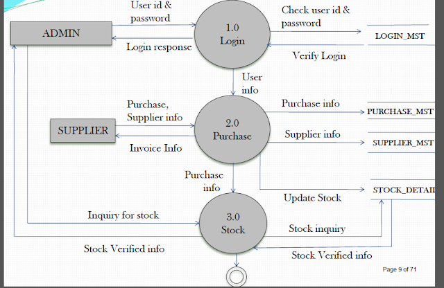
A.3.(b) We can create "Entity relationship diagram and data flow diagrams" , that are following :-
Context Level DFD:-
First Level DFD:-
Entity Relationship Diagram(ERD):-
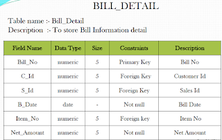
Q.4.(a) Design the system architecture and the database as per the needs of the system. You must perform normalization on relations up to 3rd normal form. The table design must include Primary and Foreign keys and constrains.
A.4.(a) Primary Key:-The PRIMARY KEY constraint uniquely identifies each record in a database table.
Primary keys must contain UNIQUE values.
A primary key column cannot contain NULL values.
Most tables should have a primary key, and each table can have only ONE primary key.
Foreign Key:-
A FOREIGN KEY in one table points to a PRIMARY KEY in another table.
Normal Forms :-
Database normalization is the process of efficiently organizing data in a database. There are two reasons of the normalization process:
- Eliminating redundant data, for example, storing the same data in more than one tables.
- Ensuring data dependencies make sense.
Both of these are worthy goals as they reduce the amount of space a database consumes and ensure that data is logically stored. Normalization consists of a series of guidelines that help guide you in creating a good database structure.
Normalization guidelines are divided into normal forms; think of form as the format or the way a database structure is laid out. The aim of normal forms is to organize the database structure so that it complies with the rules of first normal form, then second normal form, and finally third normal form.
It's your choice to take it further and go to fourth normal form, fifth normal form, and so on, but generally speaking, third normal form is enough.
Q.4.(b)Create the system flow chart or detailed process design and state transition diagrams. Also design the user input screens and output report formats.
A.4.(b) System Flow Chart :-
System flowcharts are a way of displaying how data flows in a system and how decisions are made to control events.
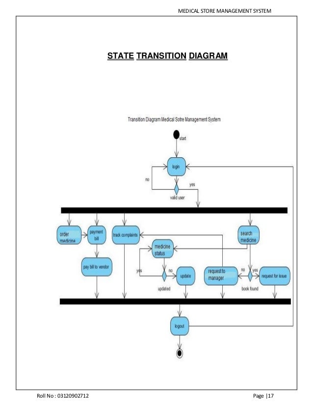
State Transition Diagram:-
State transition diagrams have been used right from the beginning in object-oriented modeling. The basic idea is to define a machine that has a number of states (hence the term finite state machine). The machine receives events from the outside world, and each event can cause the machine to transition from one state to another. For an example, take a look at figure 1. Here the machine is a bottle in a bottling plant. It begins in the empty state. In that state it can receive squirt events. If the squirt event causes the bottle to become full, then it transitions to the full state, otherwise it stays in the empty state (indicated by the transition back to its own state). When in the full state the cap event will cause it to transition to the sealed state. The diagram indicates that a full bottle does not receive squirt events, and that an empty bottle does not receive cap events. Thus you can get a good sense of what events should occur, and what effect they can have on the object.

INPUT DESIGN
OUTPUT DESIGN
Q.5.Design various unit test cases for different testing techniques/strategies.
A.5.
Test case Design Technique
Following are the typical design techniques in software
engineering:
1. Deriving test cases directly from a requirement specification
or black box test design technique. The Techniques include:
·
Boundary
Value Analysis (BVA)
·
Equivalence
Partitioning (EP)
·
Decision
Table Testing
·
State
Transition Diagrams
·
Use Case
Testing
2. Deriving test cases directly from the structure of a component
or system:
·
Statement
Coverage
·
Branch
Coverage
·
Path
Coverage
·
LCSAJ
Testing
3. Deriving test cases based on tester's experience on similar
systems or testers intuition:
·
Error
Guessing
·
Exploratory
Testing


Thanx
ReplyDeleteUr welcome
Deletehey bharti,
ReplyDeletecan you please upload 2017-18 assignment for mcsp -044 and mcs 053.
thank you
Thank u so much.
ReplyDeleteOn this page, you'll see my profile, please read this information. Quality Management Services
ReplyDelete