Q.1.Develop SRS for Grade Card Generation System for a University. SRS should be as per IEEE standard SRS template. Make necessary assumptions.
A.1. SRS:-A software requirements specification (SRS) is a document that captures complete description about how the system is expected to perform. It is usually signed off at the end of requirements engineering phase.
Qualities of SRS:
- Correct
- Unambiguous
- Complete
- Consistent
- Ranked for importance and/or stability
- Verifiable
- Modifiable
- Traceable
Types of Requirements:
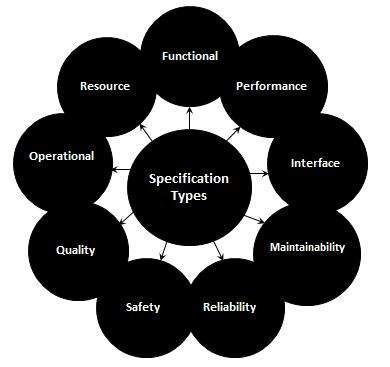
The below diagram depicts the various types of requirements that are captured during SRS.
Q.2.Draw the DFDs upto 3rd level for Grade Card Generation System for a University.
A.2. DFD(Data Flow Diagram):-
Data Flow Diagram (DFD) provides a visual representation of the flow of information (i.e. data) within a system. By drawing a Data Flow Diagram, you can tell the information provided by and delivered to someone who takes part in system processes, the information needed in order to complete the processes and the information needed to be stored and accessed.
Q.3.Draw ERD for Grade Card Generation System for a University. Make necessary assumptions.
A.3.Let us now learn how the ER Model is represented by means of an ER diagram. Any object, for example, entities, attributes of an entity, relationship sets, and attributes of relationship sets, can be represented with the help of an ER diagram.
Entity
Entities are represented by means of rectangles. Rectangles are named with the entity set they represent.

Attributes
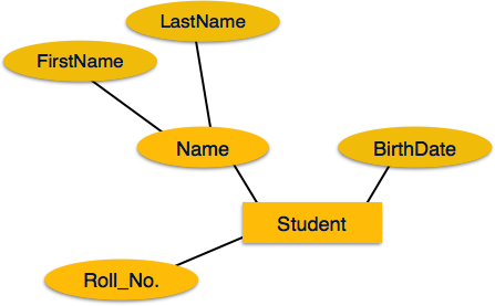
Attributes are the properties of entities. Attributes are represented by means of ellipses. Every ellipse represents one attribute and is directly connected to its entity (rectangle).

If the attributes are composite, they are further divided in a tree like structure. Every node is then connected to its attribute. That is, composite attributes are represented by ellipses that are connected with an ellipse.
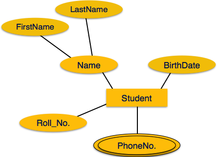
Multivalued attributes are depicted by double ellipse.
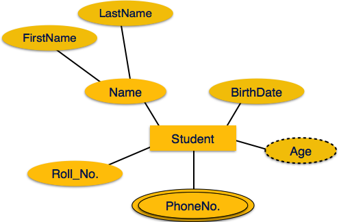
Derived attributes are depicted by dashed ellipse.
Relationship
Relationships are represented by diamond-shaped box. Name of the relationship is written inside the diamond-box. All the entities (rectangles) participating in a relationship, are connected to it by a line.
Binary Relationship and Cardinality
A relationship where two entities are participating is called a binary relationship. Cardinality is the number of instance of an entity from a relation that can be associated with the relation.
- One-to-one − When only one instance of an entity is associated with the relationship, it is marked as '1:1'. The following image reflects that only one instance of each entity should be associated with the relationship. It depicts one-to-one relationship.
- One-to-many − When more than one instance of an entity is associated with a relationship, it is marked as '1:N'. The following image reflects that only one instance of entity on the left and more than one instance of an entity on the right can be associated with the relationship. It depicts one-to-many relationship.
- Many-to-one − When more than one instance of entity is associated with the relationship, it is marked as 'N:1'. The following image reflects that more than one instance of an entity on the left and only one instance of an entity on the right can be associated with the relationship. It depicts many-to-one relationship.
- Many-to-many − The following image reflects that more than one instance of an entity on the left and more than one instance of an entity on the right can be associated with the relationship. It depicts many-to-many relationship.


Participation Constraints
- Total Participation − Each entity is involved in the relationship. Total participation is represented by double lines.
- Partial participation − Not all entities are involved in the relationship. Partial participation is represented by single lines.

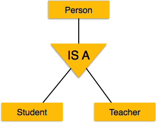
Going up in this structure is called generalization, where entities are clubbed together to represent a more generalized view. For example, a particular student named Mira can be generalized along with all the students. The entity shall be a student, and further, the student is a person. The reverse is called specialization where a person is a student, and that student is Mira.
Generalization
As mentioned above, the process of generalizing entities, where the generalized entities contain the properties of all the generalized entities, is called generalization. In generalization, a number of entities are brought together into one generalized entity based on their similar characteristics. For example, pigeon, house sparrow, crow and dove can all be generalized as Birds.

Specialization
Specialization is the opposite of generalization. In specialization, a group of entities is divided into sub-groups based on their characteristics. Take a group ‘Person’ for example. A person has name, date of birth, gender, etc. These properties are common in all persons, human beings. But in a company, persons can be identified as employee, employer, customer, or vendor, based on what role they play in the company.


This comment has been removed by a blog administrator.
ReplyDelete
ReplyDeleteYou have written wonderful article. Greetings and thank you
Bus Rental Cost Sangrur
Bus Company Ropar
Idiot. At least write things properly
ReplyDeletegood
ReplyDelete