Q.1. (a) Differentiate between Go Back-N ARQ with Selective Repeat ARQ.
Also, explain the disadvantages of stop-and-wait- ARQ in comparision
to Go Back-N ARQ protocol.
A.1.(a)

 (b) Describe the architecture of an ATM network. Also, differentiate
between two types of connections: PVC and SVC used in ATM.
(b) Describe the architecture of an ATM network. Also, differentiate
between two types of connections: PVC and SVC used in ATM.
Ans (b)

A.1.(a)
Go-Back-N Protocol and “Selective Repeat Protocol” are the sliding window protocols. The sliding window protocol is primarily an error control protocol, i.e. it is a method of error detection and error correction. The basic difference between go-back-n protocol and selective repeat protocol is that the “go-back-n protocol” retransmits all the frames that lie after the frame which is damaged or lost. The “selective repeat protocol” retransmits only that frame which is damaged or lost.
Comparison Chart :-
| BASIS FOR COMPARISON | GO-BACK-N | SELECTIVE REPEAT |
|---|---|---|
| Basic | Retransmits all the frames that sent after the frame which suspects to be damaged or lost. | Retransmits only those frames that are suspected to lost or damaged. |
| Bandwidth Utilization | If error rate is high, it wastes a lot of bandwidth. | Comparatively less bandwidth is wasted in retransmitting. |
| Complexity | Less complicated. | More complex as it require to apply extra logic and sorting and storage, at sender and receiver. |
| Window size | N-1 | <= (N+1)/2 |
| Sorting | Sorting is neither required at sender side nor at receiver side. | Receiver must be able to sort as it has to maintain the sequence of the frames. |
| Storing | Receiver do not store the frames received after the damaged frame until the damaged frame is retransmitted. | Receiver stores the frames received after the damaged frame in the buffer until the damaged frame is replaced. |
| Searching | No searching of frame is required neither on sender side nor on receiver | The sender must be able to search and select only the requested frame. |
| ACK Numbers | NAK number refer to the next expected frame number. | NAK number refer to the frame lost. |
| Use | It more often used. | It is less in practice because of its complexity. |
Definition of Go-Back-N
Go-Back-N protocol is a sliding window protocol. It is a mechanism to detect and control the error in datalink layer. During transmission of frames between sender and receiver, if a frame is damaged, lost, or an acknowledgement is lost then the action performed by sender and receiver is explained in the following content.
Ans (b)
How ATM Works
Asynchronous transfer mode (ATM) is one of many network transmission protocols included in Windows Server 2003. The most commonly used transmission protocol included in Windows Server 20003 is TCP/IP, which is a connectionless protocol. As such, TCP/IP cannot offer some of the advantages that a connection-oriented, virtual circuit, packet-switching technology, such as ATM, can. Unlike most connectionless networking protocols, ATM is a deterministic networking system — it provides predictable, guaranteed quality of service.
The ideal environment in which to use ATM is one that combines computer, voice, and video networking into a single network, and the combination of existing networks into a single infrastructure.
ATM Architecture
ATM is a combination of hardware and software that can provide either an end-to-end network or form a high-speed backbone. The structure of ATM and its software components comprise the ATM architecture, as the following illustration shows. The primary layers of ATM are the physical layer, the ATM layer, and the ATM Adaptation layer.
ATM Architectural Diagram
Each layer and sublayer is described briefly in the following table, “ATM Layers.”
ATM Layers
| Layer | Function |
|---|---|
ATM Adaptation
|
The ATM Adaptation layer facilitates the use of packets larger than a cell. Packets are segmented by the ATM interface, transmitted individually, and then reassembled on the receiving end. The ATM Adaptation Layer includes the Segmentation and Reassembly and Convergence sublayers.
|
ATM
|
The ATM layer regulates cells and cell transport and establishes and releases Virtual Circuits. The ATM layer has no sublayers
|
Physical
|
The Physical layer represents the physical medium and regulates Physical layer functions such as voltages and bit timing. The Physical layer consists of the Transmission Convergence and the Physical Medium Dependent sublayers
|
PVC vs SVC
PVC and SVC are different types of virtual circuits. “PVC” stands for “Permanent Virtual Circuit” and “SVC” stands for “Switched Virtual Circuit.” Both PVC and SVC play the main role in networks like Frame Relay and X.25. They are also used in ATM machines. To understand their differences, let us first understand what Frame Relay and X.25 networks are.
Frame Relay Networks
Frame Relay network is a protocol for a data link network. These networks are specially designed for transferring data on WANs or wide area networks. Frame Relay works on ISDN lines or fiber optics; they offer low latency and corrects errors thus reducing the overhead. The protocol provides cost-effective telecommunication which has been adopted by companies to transfer long-distance data. In recent times, the popularity of relay networks is diminishing due to the gradual migration towards IP or Internet Protocol based solutions.
Frame Relay network is a protocol for a data link network. These networks are specially designed for transferring data on WANs or wide area networks. Frame Relay works on ISDN lines or fiber optics; they offer low latency and corrects errors thus reducing the overhead. The protocol provides cost-effective telecommunication which has been adopted by companies to transfer long-distance data. In recent times, the popularity of relay networks is diminishing due to the gradual migration towards IP or Internet Protocol based solutions.
PVC (Permanent Virtual Circuit)
PVC is a virtual circuit which is available permanently. It is a type of virtual circuit where the end points do not signal the circuit. The virtual circuit values are manual. The route through the network, link-by-link is also manual. If the equipment happens to fail, the PVC also fails, and the physical network has to re-route. The permanent virtual circuit is an efficient circuit for hosts which have to communicate frequently like ATMs.
PVC is a virtual circuit which is available permanently. It is a type of virtual circuit where the end points do not signal the circuit. The virtual circuit values are manual. The route through the network, link-by-link is also manual. If the equipment happens to fail, the PVC also fails, and the physical network has to re-route. The permanent virtual circuit is an efficient circuit for hosts which have to communicate frequently like ATMs.
SVC (Switched Virtual Circuit)
SVC has to re-establish the connection every time the data has to be sent. It is a circuit established by UNI. It is basically a demand connection; the connection is initiated by the user. When the switch fails, the SVC fails, and the connection needs to be re-established.
Q.2.(a) Differentiate between switch and bridge? What are the advantages of
separating an Ethernet LAN using a bridge? Explain.SVC has to re-establish the connection every time the data has to be sent. It is a circuit established by UNI. It is basically a demand connection; the connection is initiated by the user. When the switch fails, the SVC fails, and the connection needs to be re-established.
A.2.(a) Bridge
A bridge is a product that connects a local area network (LAN) to another local area network that uses the same protocol (for example, Ethernet or token ring). You can envision a bridge as being a device that decides whether a message from you to someone else is going to the local area network in your building or to someone on the local area network in the building across the street. A bridge examines each message on a LAN, "passing" those known to be within the same LAN, and forwarding those known to be on the other interconnected LAN (or LANs).In bridging networks, computer or node addresses have no specific relationship to location. For this reason, messages are sent out to every address on the network and accepted only by the intended destination node. Bridges learn which addresses are on which network and develop a learning table so that subsequent messages can be forwarded to the right network.
Switch
A switch is a network device that selects a path or circuit for sending a unit of data to its next destination. A switch may also include the function of the router, a device or program that can determine the route and specifically what adjacent network point the data should be sent to. In general, a switch is a simpler and faster mechanism than a router, which requires knowledge about the network and how to determine the route.
A switch is a network device that selects a path or circuit for sending a unit of data to its next destination. A switch may also include the function of the router, a device or program that can determine the route and specifically what adjacent network point the data should be sent to. In general, a switch is a simpler and faster mechanism than a router, which requires knowledge about the network and how to determine the route.
(b) Write the role of DNS resolver in the DNS system. Also, explain how
does a DNS Resolver bootstrap the domain name lookup process?
Ans2(b)
Ans2(b)
DNS resolvers play a key role in converting Web links to IP addresses, acting as a link between your computer and the Internet's DNS infrastructure. A DNS resolver is a local server that stores a central database of DNS nameservers and manages DNS requests for all the clients on your network. With DNS resolvers, your computer does not need to store addresses for multiple online nameservers, a process which is difficult to manage effectively.
How DNS Works
DNS systems allow network clients to convert Universal Resource Locators, or URLs, into IP addresses. This is a key part of network operation, as computers and other devices generally need to know each other's IP address in order to communicate over a network. When you provide your computer with a Web link, the computer issues a DNS request asking for the IP address that corresponds to that address. The DNS then responds with the corresponding address, allowing the computer to communicate with the server that hosts that site.
Role of Resolvers
A DNS resolver is a server that acts as a “first port of call” in the DNS process. When a network client contacts a resolver, that resolver contacts multiple authoritative nameservers -- the servers that actually hold the IP address information -- in order to get the necessary IP address. DNS requests may involve nameservers all over the world.
DNS Resolver bootstrap the domain name lookup process
Q4. (a) Differentiate between analog and digital transmission. Give examples of each.
A4(a) Analog vs. Digital Transmission


The Domain Name System (DNS) is a hierarchical decentralized naming system for computers, services, or other resources connected to the Internet or a private network. It associates various information with domain names assigned to each of the participating entities. Most prominently, it translates more readily memorized domain names to the numerical IP addresses needed for locating and identifying computer services and devices with the underlying network protocols. By providing a worldwide, distributed directory service, the Domain Name System is an essential component of the functionality on the Internet, that has been in use since 1985.
The Domain Name System delegates the responsibility of assigning domain names and mapping those names to Internet resources by designating authoritative name servers for each domain. Network administrators may delegate authority over sub-domains of their allocated name space to other name servers. This mechanism provides distributed and fault tolerant service and was designed to avoid a single large central database.
The Domain Name System also specifies the technical functionality of the database service that is at its core. It defines the DNS protocol, a detailed specification of the data structures and data communication exchanges used in the DNS, as part of the Internet Protocol Suite. Historically, other directory services preceding DNS were not scalable to large or global directories as they were originally based on text files, prominently the HOSTS.TXT resolver.
The Internet maintains two principal namespaces, the domain name hierarchy and the Internet Protocol (IP) address spaces. The Domain Name System maintains the domain name hierarchy and provides translation services between it and the address spaces. Internet name servers and a communication protocol implement the Domain Name System.A DNS name server is a server that stores the DNS records for a domain; a DNS name server responds with answers to queries against its database.
The most common types of records stored in the DNS database are for Start of Authority (SOA), IP addresses (A and AAAA), SMTP mail exchangers (MX), name servers (NS), pointers for reverse DNS lookups (PTR), and domain name aliases (CNAME). Although not intended to be a general purpose database, DNS can store records for other types of data for either automatic lookups, such as DNSSEC records, or for human queries such as responsible person (RP) records. As a general purpose database, the DNS has also been used in combating unsolicited email (spam) by storing a real-time blackhole list. The DNS database is traditionally stored in a structured zone file.
3. (a) Explain masking used in addressing with the help of a suitable example.
Also, difference between boundary level masking and non-boundary
level masking.
Ans 3(a)
Sub network address is the address, which is depends upon the IP address and what class is used in IP address. Class of IP address may be the A, B, C. In organization we need to use sub-netting. In sub-netting IP address is split into the many sub-network address. Sub-netting allows us to split network address into several parts of internal use. If we done sub-netting then outside world only see the single network address or act as single network.
Here the term mask address is used; mask address is the address which extracts the address of the physical network address from the given IP address.
Masking is two types. First one is the boundary level masking and second one is the Non boundary level masking. If the mask address is contain only 0 or 255 then this mask is the boundary level masking. And if the mask numbers are not just 0 or 255 then it is non boundary level masking.
Masking address may be given in two ways. In first way mask address is written looks like the IP address. Ex- 255.255.0.0
And in second way the mask is given in numbers, the number is appended to IP address after slash.
Ex- 45.23.21.8/26
If the mask is given in slash number form then we need to calculate the mask address from this. For this write down the number of 1’s as given after slash. And complete the total 32 bits (if the IPv4 ) using fill 0’ in right side. And then divide in 8 bit groups. Write down the equivalent decimal value of each group.
Just like the for- 45.23.21.8/26
11111111. 11111111 .11111111 .11000000
Mask address is 255.255.255.192
Now let’s see how to find sub-network address. At first check which type of mask address is given either boundary level or non boundary level?
Sub-network address if boundary level mask is given:-
If the mask address is boundary level then it is very easy to find out the sub-network address from IP address and mask.
For this write down mask address below the IP address.
If mask bytes is 255 then IP address bytes is repeated in sub-network address.
And if bytes in the IP address that correspond to 0 in mask then put 0 in sub-network address.
Let’s take an example-
IP- 46.24.22.8
Mask- 255.255.0.0
Mask- 255.255.0.0
Sub-network address is 46.24.0.0
(b) Classify the routing protocols based on different parameters. Why is
adaptive routing superior to non adaptive routing? Explain.
Ans(b)
Adaptive routing, also called dynamic routing, is a process for determining the optimal path a data packet should follow through a network to arrive at a specific destination. Adaptive routing can be compared to a commuter taking a different route to work after learning that traffic on his usual route is backed up.
Adaptive routing uses algorithms and routing protocols that read and respond to changes in network topology. In addition to Open Shortest Path First (OSPF), other routing protocols that facilitate adaptive routing include Intermediate System to Intermediate System (IS-IS) protocol for large networks such as the internet and routing information protocol (RIP) for short-distance transport.
Advantages and challenges of adaptive routing
The purpose of adaptive routing is to help prevent packet delivery failure, improve network performance and relieve network congestion. Adaptive routing can cause nodes to become overloaded, however, due to the complex processing decisions they make. Because routers share information about the network topology, adaptive routing can be less secure than non-adaptive routing processes and require more bandwidth.
(c) Discuss the various types of encoding and modulation techniques used
in Data communication.
Ans (c)
Encoding is the process of converting the data or a given sequence of characters, symbols, alphabets etc., into a specified format, for the secured transmission of data. Decoding is the reverse process of encoding which is to extract the information from the converted format.
Data Encoding
Encoding Techniques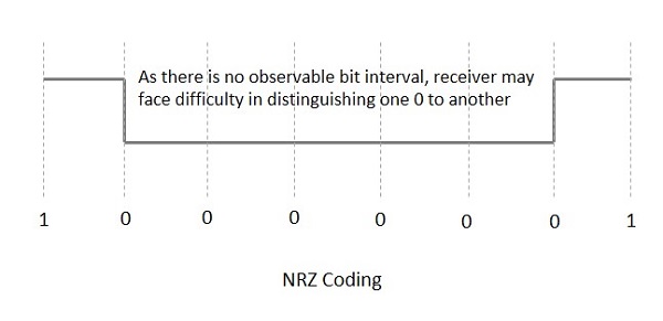 NRZ - L (NRZ – LEVEL)
Encoding Techniques
NRZ - L (NRZ – LEVEL)- Bi-phase Manchester
- Differential Manchester
Q4. (a) Differentiate between analog and digital transmission. Give examples of each.
A4(a) Analog vs. Digital Transmission
Encoding is the process of using various patterns of voltage or current levels to represent 1s and 0s of the digital signals on the transmission link.
The common types of line encoding are Unipolar, Polar, Bipolar, and Manchester.
The data encoding technique is divided into the following types, depending upon the type of data conversion.
- Analog data to Analog signals − The modulation techniques such as Amplitude Modulation, Frequency Modulation and Phase Modulation of analog signals, fall under this category.
- Analog data to Digital signals − This process can be termed as digitization, which is done by Pulse Code Modulation (PCM). Hence, it is nothing but digital modulation. As we have already discussed, sampling and quantization are the important factors in this. Delta Modulation gives a better output than PCM.
- Digital data to Analog signals − The modulation techniques such as Amplitude Shift Keying (ASK), Frequency Shift Keying (FSK), Phase Shift Keying (PSK), etc., fall under this category. These will be discussed in subsequent chapters.
- Digital data to Digital signals − These are in this section. There are several ways to map digital data to digital signals. Some of them are −
Non Return to Zero (NRZ)
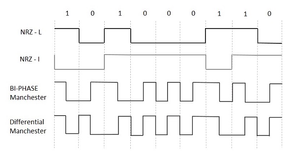
NRZ Codes has 1 for High voltage level and 0 for Low voltage level. The main behavior of NRZ codes is that the voltage level remains constant during bit interval. The end or start of a bit will not be indicated and it will maintain the same voltage state, if the value of the previous bit and the value of the present bit are same.
The following figure explains the concept of NRZ coding.
If the above example is considered, as there is a long sequence of constant voltage level and the clock synchronization may be lost due to the absence of bit interval, it becomes difficult for the receiver to differentiate between 0 and 1.
There are two variations in NRZ namely −
There is a change in the polarity of the signal, only when the incoming signal changes from 1 to 0 or from 0 to 1. It is the same as NRZ, however, the first bit of the input signal should have a change of polarity.
NRZ - I (NRZ – INVERTED)
If a 1 occurs at the incoming signal, then there occurs a transition at the beginning of the bit interval. For a 0 at the incoming signal, there is no transition at the beginning of the bit interval.
NRZ codes has a disadvantage that the synchronization of the transmitter clock with the receiver clock gets completely disturbed, when there is a string of 1s and 0s. Hence, a separate clock line needs to be provided.
Bi-phase Encoding
The signal level is checked twice for every bit time, both initially and in the middle. Hence, the clock rate is double the data transfer rate and thus the modulation rate is also doubled. The clock is taken from the signal itself. The bandwidth required for this coding is greater.
There are two types of Bi-phase Encoding.
Bi-phase Manchester
In this type of coding, the transition is done at the middle of the bit-interval. The transition for the resultant pulse is from High to Low in the middle of the interval, for the input bit 1. While the transition is from Low to High for the input bit 0.
Differential Manchester
In this type of coding, there always occurs a transition in the middle of the bit interval. If there occurs a transition at the beginning of the bit interval, then the input bit is 0. If no transition occurs at the beginning of the bit interval, then the input bit is 1.
The following figure illustrates the waveforms of NRZ-L, NRZ-I, Bi-phase Manchester and Differential Manchester coding for different digital inputs.
Analog transmission is a method of conveying voice, data, image, signal, or video information. It uses a continuous signal varying in amplitude, phase, or another property that is in proportion to a specific characteristic of a variable. Analog transmission could mean that the transmission is a transfer of an analog source signal which uses an analog modulation method (or a variance of one or more properties of high frequency periodic waveform, also known as a carrier signal). FM and AM are examples of such a modulation. The transmission could also use no modulation at all. It is most notably an information signal that is constantly varying.
Data transmission (also known as digital transmission or digital communications) is a literal transfer of data over a point to point (or point to multipoint) transmission medium –such as copper wires, optical fibres, wireless communications media, or storage media. The data that is to be transferred is often represented as an electro-magnetic signal (such as a microwave). Digital transmission transfers messages discretely. These messages are represented by a sequence of pulses via a line code. However, these messages can also be represented by a limited set of wave forms that always vary. Either way, they are represented using a digital modulation method.
Analog transmission is capable of being conveyed in a no fewer than four ways: through a twisted pair or coax cable, through a fibre optic cable, through the air, or through water. There are, however, only two basic types of analog transmission. The first is known as amplitude modulation (or AM). This is a technique used in electronic communication and works by alternating the strength of a transmitted signal in relation to the information that is being sent. The second is known as frequency modulation (or FM). This type of communication conveys information over a carrier wave, just as AM transmission. However, FM communication alternates the frequency of the transmitted signal.
Data that is transmitted via digital transmission may be digital messages that have origins for a data source (a computer or a keyboard, for example). However, this transmitted data may also be from an analog signal (a phone call or a video signal, for example). It may then be digitized into a bit stream using pulse code modulation (or PCM) –or even more advanced source coding schemes. The coding of the data is carried out using codec equipment.
(b) List the requirements to connect two different networks (Ethernet and
Token ring) in the lower layers?
Ans(b)
Types of Network Protocols
Types of Network Protocols
- Ethernet
- Local Talk
- Token Ring
- FDDI
- ATM
Rules of Network Protocol include guidelines that regulate the following characteristics of a network: access method, allowed physical topologies, types of cabling, and speed of data transfer.
The most common network protocols are:
The followings are some commonly used network symbols to draw different kinds of network protocols.
Ethernet
The Ethernet protocol is by far the most widely used one. Ethernet uses an access method called CSMA/CD (Carrier Sense Multiple Access/Collision Detection). This is a system where each computer listens to the cable before sending anything through the network. If the network is clear, the computer will transmit. If some other nodes have already transmitted on the cable, the computer will wait and try again when the line is clear. Sometimes, two computers attempt to transmit at the same instant. A collision occurs when this happens. Each computer then backs off and waits a random amount of time before attempting to retransmit. With this access method, it is normal to have collisions. However, the delay caused by collisions and retransmitting is very small and does not normally effect the speed of transmission on the network.
The Ethernet protocol allows for linear bus, star, or tree topologies. Data can be transmitted over wireless access points, twisted pair, coaxial, or fiber optic cable at a speed of 10 Mbps up to 1000 Mbps.
Fast Ethernet
To allow for an increased speed of transmission, the Ethernet protocol has developed a new standard that supports 100 Mbps. This is commonly called Fast Ethernet. Fast Ethernet requires the application of different, more expensive network concentrators/hubs and network interface cards. In addition, category 5 twisted pair or fiber optic cable is necessary. Fast Ethernet is becoming common in schools that have been recently wired.
Local Talk
Local Talk is a network protocol that was developed by Apple Computer, Inc. for Macintosh computers. The method used by Local Talk is called CSMA/CA (Carrier Sense Multiple Access with Collision Avoidance). It is similar to CSMA/CD except that a computer signals its intent to transmit before it actually does so. Local Talk adapters and special twisted pair cable can be used to connect a series of computers through the serial port. The Macintosh operating system allows the establishment of a peer-to-peer network without the need for additional software. With the addition of the server version of AppleShare software, a client/server network can be established.
The Local Talk protocol allows for linear bus, star, or tree topologies using twisted pair cable. A primary disadvantage of Local Talk is low speed. Its speed of transmission is only 230 Kbps.
Token Ring
The Token Ring protocol was developed by IBM in the mid-1980s. The access method used involves token-passing. In Token Ring, the computers are connected so that the signal travels around the network from one computer to another in a logical ring. A single electronic token moves around the ring from one computer to the next. If a computer does not have information to transmit, it simply passes the token on to the next workstation. If a computer wishes to transmit and receives an empty token, it attaches data to the token. The token then proceeds around the ring until it comes to the computer for which the data is meant. At this point, the data is captured by the receiving computer. The Token Ring protocol requires a star-wired ring using twisted pair or fiber optic cable. It can operate at transmission speeds of 4 Mbps or 16 Mbps. Due to the increasing popularity of Ethernet, the use of Token Ring in school environments has decreased.
(c) Explain the limitations of distance vector routing algorithm.
Ans(c)


(d) Explain the significance and use of different fields of TCP header and
IP header with the help of neat diagrams.
Ans(d) IP Layer in TCP/IP Suite
IP protocol is one of the main protocols in the TCP/IP stack.
It is in the form of IP datagrams that all the TCP, UDP, ICMP and IGMP data travels over the network.
IP is connection less and unreliable protocol. It is connection less in the sense that no state related to IP datagrams is maintained either on source or destination side and it is unreliable in the sense that it not guaranteed that an IP data gram will get delivered to the destination or not.
If an IP datagram encounters some error at the destination or at some intermediate host (while traveling from source to destination) then the IP datagram is generally discarded and an ICMP error message is sent back to the source.
As can be seen from the image above, the IP protocol sits at the layer-2 of TCP/IP protocol suite ie the Internet layer. Another point worth noting here is how the data is packed in TCP/IP suite. If we analyze the figure above, we see :
- The application layer sends the data (to be transferred to remote destination ) to the transport layer.
- The transport layer puts its header in the beginning and sends this complete packet (TCP-header + app-data) to the IP layer.
- On the same lines, The IP layer puts its header in front of the data received from TCP (Note that data received from TCP = TCP-header + app-data).
- So now the structure of IP datagram becomes IP-header + TCP-header + app-data.
- This IP datagram is passed to the ethernet layer which on the same lines adds its own header to IP datagram and then the whole packet is transmitted over network.
On the destination host, the reverse process happens. This means that each layer reads its own header in the packet and then strips the header so that finally application receives the app-data.
IP Header
- Protocol Version(4 bits) : This is the first field in the protocol header. This field occupies 4 bits. This signifies the current IP protocol version being used. Most common version of IP protocol being used is version 4 while version 6 is out in market and fast gaining popularity.
- Header Length(4 bits) : This field provides the length of the IP header. The length of the header is represented in 32 bit words. This length also includes IP options (if any). Since this field is of 4 bits so the maximum header length allowed is 60 bytes. Usually when no options are present then the value of this field is 5. Here 5 means five 32 bit words ie 5 *4 = 20 bytes.
- Type of service(8 bits) : The first three bits of this field are known as precedence bits and are ignored as of today. The next 4 bits represent type of service and the last bit is left unused. The 4 bits that represent TOS are : minimize delay, maximize throughput, maximize reliability and minimize monetary cost.
- Total length(16 bits): This represents the total IP datagram length in bytes. Since the header length (described above) gives the length of header and this field gives total length so the length of data and its starting point can easily be calculated using these two fields. Since this is a 16 bit field and it represents length of IP datagram so the maximum size of IP datagram can be 65535 bytes. When IP fragmentation takes place over the network then value of this field also changes. There are cases when IP datagrams are very small in length but some data links like ethernet pad these small frames to be of a minimum length ie 46 bytes. So to know the exact length of IP header in case of ethernet padding this field comes in handy.
- Identification(16 bits): This field is used for uniquely identifying the IP datagrams. This value is incremented every-time an IP datagram is sent from source to the destination. This field comes in handy while reassembly of fragmented IP data grams.
- Flags(3 bits): This field comprises of three bits. While the first bit is kept reserved as of now, the next two bits have their own importance. The second bit represents the ‘Don’t Fragment’ bit. When this bit is set then IP datagram is never fragmented, rather its thrown away if a requirement for fragment arises. The third bit represents the ‘More Fragment’ bit. If this bit is set then it represents a fragmented IP datagram that has more fragments after it. In case of last fragment of an IP datagram this bit is not set signifying that this is the last fragment of a particular IP datagram.
- Fragment offset(13 bits): In case of fragmented IP data grams, this field contains the offset( in terms of 8 bytes units) from the start of IP datagram. So again, this field is used in reassembly of fragmented IP datagrams.
- Time to live(8 bits) : This value represents number of hops that the IP datagram will go through before being discarded. The value of this field in the beginning is set to be around 32 or 64 (lets say) but at every hop over the network this field is decremented by one. When this field becomes zero, the data gram is discarded. So, we see that this field literally means the effective lifetime for a datagram on network.
- Protocol(8 bits) : This field represents the transport layer protocol that handed over data to IP layer. This field comes in handy when the data is demultiplex-ed at the destination as in that case IP would need to know which protocol to hand over the data to.
- Header Checksum(16 bits) : This fields represents a value that is calculated using an algorithm covering all the fields in header (assuming this very field to be zero). This value is calculated and stored in header when IP data gram is sent from source to destination and at the destination side this checksum is again calculated and verified against the checksum present in header. If the value is same then the datagram was not corrupted else its assumed that data gram was received corrupted. So this field is used to check the integrity of an IP datagram.
- Source and destination IP(32 bits each) : These fields store the source and destination address respectively. Since size of these fields is 32 bits each so an IP address os maximum length of 32 bits can be used. So we see that this limits the number of IP addresses that can be used. To counter this problem, IP V6 has been introduced which increases this capacity.
- Options(Variable length) : This field represents a list of options that are active for a particular IP datagram. This is an optional field that could be or could not be present. If any option is present in the header then the first byte is represented as follows :
| 0 | 1 | 2 | 3 | 4 | 5 | 6 | 7 |
| copy flag | option class | option num | |||||
- In the description above, the ‘copy flag’ means that copy this option to all the fragments in case this IP datagram gets fragmented. The ‘option class’ represents the following values : 0 -> control, 1-> reserved, 2 -> debugging and measurement, and 3 -> reserved. Some of the options are given below :
| class | number | length | description |
| 0 | 0 | – | end of option list |
| 0 | 1 | – | no operation |
| 0 | 2 | 11 | security |
| 0 | 3 | var. | loose source routing |
| 0 | 9 | var. | strict source routing |
| 0 | 7 | var. | record route |
| 0 | 8 | 4 | stream id |
| 2 | 4 | var. | INTERNET time stamp |
- Data: This field contains the data from the protocol layer that has handed over the data to IP layer. Generally this data field contains the header and data of the transport layer protocols. Please note that each TCP/IP layer protocol attaches its own header at the beginning of the data it receives from other layers in case of source host and in case of destination host each protocol strips its own header and sends the rest of the data to the next layer.
This comment has been removed by a blog administrator.
ReplyDeleteThis comment has been removed by a blog administrator.
ReplyDelete