Q.1.
A.1.
Q.2.
A.2.


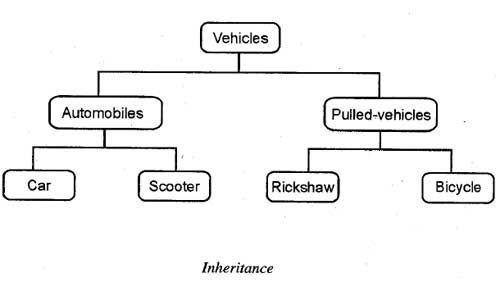
 In the same way, OOP allows one class to inherit the properties of another class or classes. The class, which is inherited by the other classes, is known as superclass or base class or parent class and the class, which inherits the properties of the base class, is called sub class or derived class or child class. The sub class can further be inherited to form other derived classes. For example, car and scooter are the derived classes of automobiles and rickshaw and bicycle are the derived classes of pulled vehicles


A.1.
OOAD is a software engineering approach that models and designs a system as a group of interacting objects. Object is the term used to describe some entity or “thing” of interest. These objects are typically modeled after real world entities or concepts. For the business analyst, these would be the real-world entities that arise within the business (invoice, product, contract, etc).
Objects have attributes which can be set to specific values. This defines the state of the object. Objects also have methods or functions which define their behavior.
Here is a quick example for illustrative purposes. Consider the real world object “Car”. Our car has attributes that can be defined with specific values such as,
- make = ford
- model = escape
- year = 2002
- color = green
- maximum speed = 130 mph
- current speed = 50 mph
- ideal tire pressure = 35 psi
- current tire pressure = 31 psi
- remaining fuel = 12 gallons
Each of these attributes define the “state” of the vehicle. They describe the car as it is at some point in time. Additionally, the car has certain “behaviors” such as
- accelerate ()
- decelerate ()
- refuel ()
- fill tires ()
Each of these behaviors of the real world object can be represented as a method of the object when designing the system (methods are also known as a functions in some programming languages). These methods can change the values of the attributes causing a change in state.
OOAD is comprised of two parts:
(1) object oriented analysis
(2) object oriented design
Models of different types can be created to reflect the static structure, dynamic behavior, and run-time deployment of the collaborating objects of a system.
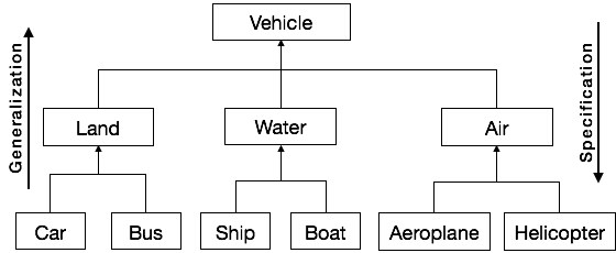
Generalization and Specialization
Generalization and specialization represent a hierarchy of relationships between classes, where subclasses inherit from super-classes.
Generalization
In the generalization process, the common characteristics of classes are combined to form a class in a higher level of hierarchy, i.e., subclasses are combined to form a generalized super-class. It represents an “is – a – kind – of” relationship. For example, “car is a kind of land vehicle”, or “ship is a kind of water vehicle”.
Specialization
Specialization is the reverse process of generalization. Here, the distinguishing features of groups of objects are used to form specialized classes from existing classes. It can be said that the subclasses are the specialized versions of the super-class.
The following figure shows an example of generalization and specialization.
Q.2.
A.2.
Class diagram is a static diagram. It represents the static view of an application. Class diagram is not only used for visualizing, describing, and documenting different aspects of a system but also for constructing executable code of the software application.
Class diagram describes the attributes and operations of a class and also the constraints imposed on the system. The class diagrams are widely used in the modeling of objectoriented systems because they are the only UML diagrams, which can be mapped directly with object-oriented languages.
Class diagram shows a collection of classes, interfaces, associations, collaborations, and constraints. It is also known as a structural diagram.

Purpose of Class Diagrams
The purpose of class diagram is to model the static view of an application. Class diagrams are the only diagrams which can be directly mapped with object-oriented languages and thus widely used at the time of construction.
UML diagrams like activity diagram, sequence diagram can only give the sequence flow of the application, however class diagram is a bit different. It is the most popular UML diagram in the coder community.
The purpose of the class diagram can be summarized as −
- Analysis and design of the static view of an application.
- Describe responsibilities of a system.
- Base for component and deployment diagrams.
- Forward and reverse engineering.
How to Draw a Class Diagram?
Class diagrams are the most popular UML diagrams used for construction of software applications. It is very important to learn the drawing procedure of class diagram.
Class diagrams have a lot of properties to consider while drawing but here the diagram will be considered from a top level view.
Class diagram is basically a graphical representation of the static view of the system and represents different aspects of the application. A collection of class diagrams represent the whole system.
The following points should be remembered while drawing a class diagram −
- The name of the class diagram should be meaningful to describe the aspect of the system.
- Each element and their relationships should be identified in advance.
- Responsibility (attributes and methods) of each class should be clearly identified
- For each class, minimum number of properties should be specified, as unnecessary properties will make the diagram complicated.
- Use notes whenever required to describe some aspect of the diagram. At the end of the drawing it should be understandable to the developer/coder.
- Finally, before making the final version, the diagram should be drawn on plain paper and reworked as many times as possible to make it correct.
Q.3.
A.3. To model a system, the most important aspect is to capture the dynamic behavior. Dynamic behavior means the behavior of the system when it is running/operating.
Only static behavior is not sufficient to model a system rather dynamic behavior is more important than static behavior. In UML, there are five diagrams available to model the dynamic nature and use case diagram is one of them. Now as we have to discuss that the use case diagram is dynamic in nature, there should be some internal or external factors for making the interaction.
These internal and external agents are known as actors. Use case diagrams consists of actors, use cases and their relationships. The diagram is used to model the system/subsystem of an application. A single use case diagram captures a particular functionality of a system.
Hence to model the entire system, a number of use case diagrams are used.
Purpose of Use Case Diagrams
The purpose of use case diagram is to capture the dynamic aspect of a system. However, this definition is too generic to describe the purpose, as other four diagrams (activity, sequence, collaboration, and Statechart) also have the same purpose. We will look into some specific purpose, which will distinguish it from other four diagrams.
Use case diagrams are used to gather the requirements of a system including internal and external influences. These requirements are mostly design requirements. Hence, when a system is analyzed to gather its functionalities, use cases are prepared and actors are identified.
When the initial task is complete, use case diagrams are modelled to present the outside view.
In brief, the purposes of use case diagrams can be said to be as follows −
- Used to gather the requirements of a system.
- Used to get an outside view of a system.
- Identify the external and internal factors influencing the system.
- Show the interaction among the requirements are actors.
Q.4.
A.4. Sequence Digram
Q.5.
A.5.(a)
Inheritance can be defined as the process whereby an object of a class acquires characteristics from the object of the other class. All the objects of a similar kind are grouped together to form a class. However, sometimes a situation arises when different objects cannot be combined together under a single group as they share only some common characteristics. In this situation, the classes are defined in such a way that the common features are combined to form a generalized class and the specific features are combined to form a specialized class. The specialized class is defined in such a way that in addition to the individual characteristics and functions, it also inherits all the properties and the functions of its generalized class.
For example, in the real world, all the vehicles cannot be automobiles-some of them are pulled-vehicles also. Thus, car and scooter both are vehicles that come under the category of automobiles. Similar, rickshaw and bicycle are the vehicles that come under the category of pulled-vehicles. In other words, automobiles and pulled-vehicles inherit the common properties of the vehicle class and also have some other properties that are not common and differentiate them. Thus, the vehicles class is the generalization of automobiles and pulled-vehicles class, and automobiles and pulled-vehicles classes are the specialized versions of the vehicles class. Note that while inheriting the vehicle class, the automobiles and pulled-vehicles do not modify the properties of the vehicle class, however, can add new properties that are exclusive for them.
Inheritance can be of two types, namely, single inheritance and multiple inheritance. If a class acquires properties from a single class, it is termed as single inheritance and if it acquires characteristics from two or more classes, it is known as multiple inheritance.
The main advantage of inheritance is reusability. The existing classes can be simply re-used in new software instead of writing a new code. However, new features can be added without altering or modifying the features of the existing class.
While inheriting a base class, a derived class not only inherits the data and functions of its base class, but can also provide a different implementation (definition) for the functions of the base class. In such a case, the base class mayor may not provide an implementation for its function. It only provides the interface for the functions.
Q.5.(b)
A.5.(b)
The dynamic model represents the time–dependent aspects of a system. It is concerned with the temporal changes in the states of the objects in a system. The main concepts are:
- State, which is the situation at a particular condition during the lifetime of an object.
- Transition, a change in the state
- Event, an occurrence that triggers transitions
- Action, an uninterrupted and atomic computation that occurs due to some event, and
- Concurrency of transitions.
A state machine models the behavior of an object as it passes through a number of states in its lifetime due to some events as well as the actions occurring due to the events. A state machine is graphically represented through a state transition diagram.
States and State Transitions
State
The state is an abstraction given by the values of the attributes that the object has at a particular time period. It is a situation occurring for a finite time period in the lifetime of an object, in which it fulfils certain conditions, performs certain activities, or waits for certain events to occur. In state transition diagrams, a state is represented by rounded rectangles.
Parts of a state
- Name : A string differentiates one state from another. A state may not have any name.
- Entry/Exit Actions : It denotes the activities performed on entering and on exiting the state.
- Internal Transitions : The changes within a state that do not cause a change in the state.
- Sub–states : States within states.
Initial and Final States
The default starting state of an object is called its initial state. The final state indicates the completion of execution of the state machine. The initial and the final states are pseudo-states, and may not have the parts of a regular state except name. In state transition diagrams, the initial state is represented by a filled black circle. The final state is represented by a filled black circle encircled within another unfilled black circle.
Transition
A transition denotes a change in the state of an object. If an object is in a certain state when an event occurs, the object may perform certain activities subject to specified conditions and change the state. In this case, a state−transition is said to have occurred. The transition gives the relationship between the first state and the new state. A transition is graphically represented by a solid directed arc from the source state to the destination state.
The five parts of a transition are:
- Source State : The state affected by the transition.
- Event Trigger : The occurrence due to which an object in the source state undergoes a transition if the guard condition is satisfied.
- Guard Condition : A Boolean expression which if True, causes a transition on receiving the event trigger.
- Action : An un-interruptible and atomic computation that occurs on the source object due to some event.
- Target State : The destination state after completion of transition.
Q.6.
A.6.
Functional Modelling gives the process perspective of the object-oriented analysis model and an overview of what the system is supposed to do. It defines the function of the internal processes in the system with the aid of Data Flow Diagrams (DFDs). It depicts the functional derivation of the data values without indicating how they are derived when they are computed, or why they need to be computed.
Data Flow Diagrams
Functional Modelling is represented through a hierarchy of DFDs. The DFD is a graphical representation of a system that shows the inputs to the system, the processing upon the inputs, the outputs of the system as well as the internal data stores. DFDs illustrate the series of transformations or computations performed on the objects or the system, and the external controls and objects that affect the transformation.
Rumbaughetal. have defined DFD as, “A data flow diagram is a graph which shows the flow of data values from their sources in objects through processes that transform them to their destinations on other objects.”
The four main parts of a DFD are:
- Processes,
- Data Flows,
- Actors, and
- Data Stores.
The other parts of a DFD are:
- Constraints, and
- Control Flows.
Features of a DFD
Processes
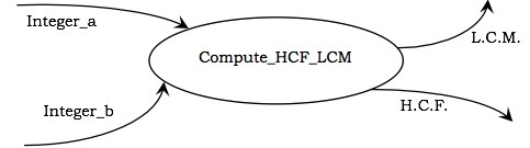
Processes are the computational activities that transform data values. A whole system can be visualized as a high-level process. A process may be further divided into smaller components. The lowest-level process may be a simple function.
Representation in DFD : A process is represented as an ellipse with its name written inside it and contains a fixed number of input and output data values.
Example : The following figure shows a process Compute_HCF_LCM that accepts two integers as inputs and outputs their HCF (highest common factor) and LCM (least common multiple).
Data Flows
Data flow represents the flow of data between two processes. It could be between an actor and a process, or between a data store and a process. A data flow denotes the value of a data item at some point of the computation. This value is not changed by the data flow.
Q.7.
A.7.
Q.8.
A.8. (a)
Associations
An association is a relationship between two classes represented by a solid line. Associations are bi-directional by default, so both classes know about each other and about the relationship between them. Either end of the line can have a role name and multiplicity. In the example, Student has the role of "tenant" in relation to Apartment and Apartment has the role of "accommodation" in relation to Student. Also, any instance of Apartment can be associated with up to four students and any student could be associated with 0 or 1 Apartment (a student either has an apartment to live in or does not).
Associations can also be unidirectional, where one class knows about the other class and the relationship but the other class does not. Such associations require an open arrowhead to point to the class that is known and only the known class can have a role name and multiplicity. In the example, the Customer class knows about any number of products purchased but the Product class knows nothing about any customer. The multiplicity "0..*" means zero or more.
An alternative to using role names is to provide a single name for an association centered between the two classes. A direction indicator can also be used to show the direction of the name, but is not necessary if the direction is obvious:
An association can also link a class to itself. Such an association is reflexive:
Q.8.
A.8.(b)
The uncontrolled execution of concurrent transactions in a multi-user environment can lead to various problems. The three main problems and examples of how they can occur are listed below:
Lost Updates
This problem occurs when two transactions, accessing the same data items, have their operations interleaved in such a way, that one transaction will access the data before the other has applied any updates.
This problem occurs when two transactions, accessing the same data items, have their operations interleaved in such a way, that one transaction will access the data before the other has applied any updates.
| Transaction1 | Transaction2 | Operation | Data Value |
| Read Flight Information | seats = 15 | ||
| Read Flight Information | seats = 15 | ||
| Book 2 seats | seats = seats -2 | ||
| Book 1 seat | seats = seats -1 | ||
| Write seats | seats = 13 | ||
| Write seats | seats = 14 |
In this simplified example, you can see that the operations are interleaved in such a way that Transaction 2 had access to the data before Transaction 1 could reduce the seats by 1. Transaction 2's operation of reducing the seats by 2 has been overwritten, resulting in an incorrect value of available seats.
This violates the Serializability property which requires that the results of interleaving must leave the database with the same results as serial processing. It also violates the Isolation property of allowing a transaction to complete without interference from another.
Yay!! MCS-032 also in. Great. Thanks :)
ReplyDeleteTHANKS
ReplyDeletewelcome
ReplyDeleteSir please upload MCA forth sem solve assignment
ReplyDeleteUpdated..
Delete