Q.1.What is OOAD? Critically evaluate advantage of OOAD over structured analysis and design of system.
A.1. OOAD
Object-oriented analysis and design (OOAD) is a popular technical approach for analyzing, designing an application, system, or business by applying the object-oriented paradigm and visual modeling throughout the development life cycles to foster better stakeholder communication and product quality.
Structured Analysis vs. Object Oriented Analysis
The Structured Analysis/Structured Design (SASD) approach is the traditional approach of software development based upon the waterfall model. The phases of development of a system using SASD are:
- Feasibility Study
- Requirement Analysis and Specification
- System Design
- Implementation
- Post-implementation Review
Now, we will look at the relative advantages and disadvantages of structured analysis approach and object-oriented analysis approach.
Advantages/Disadvantages of Object Oriented Analysis
| Advantages | Disadvantages |
|---|---|
| Focuses on data rather than the procedures as in Structured Analysis. | Functionality is restricted within objects. This may pose a problem for systems which are intrinsically procedural or computational in nature. |
| The principles of encapsulation and data hiding help the developer to develop systems that cannot be tampered by other parts of the system. | It cannot identify which objects would generate an optimal system design. |
| The principles of encapsulation and data hiding help the developer to develop systems that cannot be tampered by other parts of the system. | The object-oriented models do not easily show the communications between the objects in the system. |
| It allows effective management of software complexity by the virtue of modularity. | All the interfaces between the objects cannot be represented in a single diagram. |
| It can be upgraded from small to large systems at a greater ease than in systems following structured analysis. |
Advantages/Disadvantages of Structured Analysis
| Advantages | Disadvantages |
|---|---|
| As it follows a top-down approach in contrast to bottom-up approach of object-oriented analysis, it can be more easily comprehended than OOA. | In traditional structured analysis models, one phase should be completed before the next phase. This poses a problem in design, particularly if errors crop up or requirements change. |
| It is based upon functionality. The overall purpose is identified and then functional decomposition is done for developing the software. The emphasis not only gives a better understanding of the system but also generates more complete systems. | The initial cost of constructing the system is high, since the whole system needs to be designed at once leaving very little option to add functionality later. |
| The specifications in it are written in simple English language, and hence can be more easily analyzed by non-technical personnel. | It does not support reusability of code. So, the time and cost of development is inherently high. |
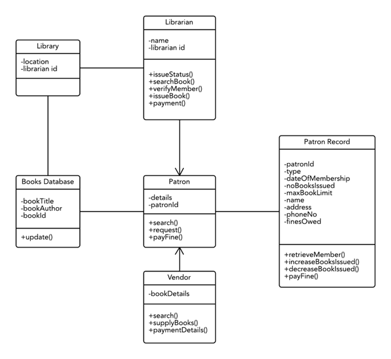
Q.2.What is class diagram ? Draw class diagram for Library Management System.
A.2.
The class diagram is a static diagram. It represents the static view of an application. Class diagram is not only used for visualizing, describing and documenting different aspects of a system but also for constructing executable code of the software application.
The class diagram describes the attributes and operations of a class and also the constraints imposed on the system. The class diagrams are widely used in the modelling of object oriented systems because they are the only UML diagrams which can be mapped directly with object oriented languages.
The class diagram shows a collection of classes, interfaces, associations, collaborations and constraints. It is also known as a structural diagram.
Purpose:
The purpose of the class diagram is to model the static view of an application. The class diagrams are the only diagrams which can be directly mapped with object oriented languages and thus widely used at the time of construction.
The UML diagrams like activity diagram, sequence diagram can only give the sequence flow of the application but class diagram is a bit different. So it is the most popular UML diagram in the coder community.
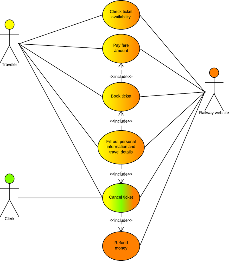
Q.3.What is advantage of use case diagram? Draw use case diagram for Online Railway Reservation System.
A.3.
To model a system the most important aspect is to capture the dynamic behaviour. To clarify a bit in details, dynamic behaviour means the behaviour of the system when it is running /operating.
So only static behaviour is not sufficient to model a system rather dynamic behaviour is more important than static behaviour. In UML there are five diagrams available to model dynamic nature and use case diagram is one of them. Now as we have to discuss that the use case diagram is dynamic in nature there should be some internal or external factors for making the interaction.
These internal and external agents are known as actors. So use case diagrams are consists of actors, use cases and their relationships. The diagram is used to model the system/subsystem of an application. A single use case diagram captures a particular functionality of a system.
So to model the entire system numbers of use case diagrams are used.
Purpose
The purpose of use case diagram is to capture the dynamic aspect of a system. But this definition is too generic to describe the purpose.
Because other four diagrams (activity, sequence, collaboration and Statechart) are also having the same purpose. So we will look into some specific purpose which will distinguish it from other four diagrams.
Use case diagrams are used to gather the requirements of a system including internal and external influences. These requirements are mostly design requirements. So when a system is analyzed to gather its functionalities use cases are prepared and actors are identified.
Now when the initial task is complete use case diagrams are modelled to present the outside view.
Q.4.Draw a sequence diagram for online university admission system.
A.4. Sequence diagrams describe interactions among classes in terms of an exchange of messages over time. They're also called event diagrams. A sequence diagram is a good way to visualize and validate various runtime scenarios. These can help to predict how a system will behave and to discover responsibilities a class may need to have in the process of modeling a new system.
Types of Messages in Sequence Diagrams
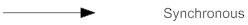
Synchronous Message
A synchronous message requires a response before the interaction can continue. It's usually drawn using a line with a solid arrowhead pointing from one object to another.
A synchronous message requires a response before the interaction can continue. It's usually drawn using a line with a solid arrowhead pointing from one object to another.
Asynchronous Message
Asynchronous messages don't need a reply for interaction to continue. Like synchronous messages, they are drawn with an arrow connecting two lifelines; however, the arrowhead is usually open and there's no return message depicted.
Asynchronous messages don't need a reply for interaction to continue. Like synchronous messages, they are drawn with an arrow connecting two lifelines; however, the arrowhead is usually open and there's no return message depicted.


Reply or Return Message
A reply message is drawn with a dotted line and an open arrowhead pointing back to the original lifeline.
A reply message is drawn with a dotted line and an open arrowhead pointing back to the original lifeline.

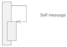
Self Message
A message an object sends to itself, usually shown as a U shaped arrow pointing back to itself.
A message an object sends to itself, usually shown as a U shaped arrow pointing back to itself.
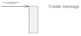
Create Message
This is a message that creates a new object. Similar to a return message, it's depicted with a dashed line and an open arrowhead that points to the rectangle representing the object created.
This is a message that creates a new object. Similar to a return message, it's depicted with a dashed line and an open arrowhead that points to the rectangle representing the object created.
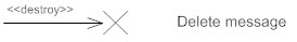
Delete Message
This is a message that destroys an object. It can be shown by an arrow with an x at the end.
This is a message that destroys an object. It can be shown by an arrow with an x at the end.
Found Message
A message sent from an unknown recipient, shown by an arrow from an endpoint to a lifeline.
A message sent from an unknown recipient, shown by an arrow from an endpoint to a lifeline.
Lost Message
A message sent to an unknown recipient. It's shown by an arrow going from a lifeline to an endpoint, a filled circle or an x.
A message sent to an unknown recipient. It's shown by an arrow going from a lifeline to an endpoint, a filled circle or an x.
Sequence diagram for online university admission system.

Q.5.
(a) What is generalization? Explain generalization and inheritance with the help of an example.
A.5.
Terms such as superclass, subclass, or inheritance come to mind when thinking about the object-oriented approach. These concepts are very important when dealing with object-oriented programming languages such as Java, Smalltalk, or C++. For modeling classes that illustrate technical concepts they are secondary. The reason for this is that modeling relevant objects or ideas from the real world gives little opportunity for using inheritance (compare the class diagram of our case study). Nevertheless, we would like to further introduce these terms at this point in Figure 4.26:
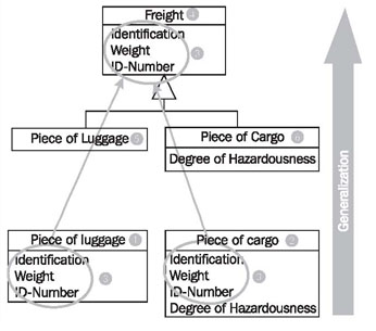
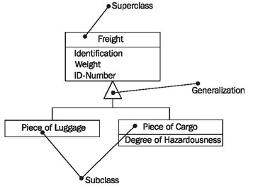 Generalization is the process of extracting shared characteristics from two or more classes, and combining them into a generalized superclass. Shared characteristics can be attributes, associations, or methods.
the classes Piece of Luggage (1) and Piece of Cargo (2) partially share the same attributes. From a domain perspective, the two classes are also very similar. During generalization, the shared characteristics (3) are combined and used to create a new superclass Freight (4). Piece of Luggage (5) and Piece of Cargo (6) become subclasses of the class Freight.
The shared attributes (3) are only listed in the superclass, but also apply to the two subclasses, even though they are not listed there.
Generalization is the process of extracting shared characteristics from two or more classes, and combining them into a generalized superclass. Shared characteristics can be attributes, associations, or methods.
the classes Piece of Luggage (1) and Piece of Cargo (2) partially share the same attributes. From a domain perspective, the two classes are also very similar. During generalization, the shared characteristics (3) are combined and used to create a new superclass Freight (4). Piece of Luggage (5) and Piece of Cargo (6) become subclasses of the class Freight.
The shared attributes (3) are only listed in the superclass, but also apply to the two subclasses, even though they are not listed there.
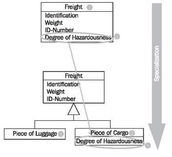
In contrast to generalization, specialization means creating new subclasses from an existing class. If it turns out that certain attributes, associations, or methods only apply to some of the objects of the class, a subclass can be created. The most inclusive class in a generalization/specialization is called the superclass and is generally located at the top of the diagram. The more specific classes are called subclasses and are generally placed below the superclass.
The class Freight (1) has the attribute Degree of Hazardousness (2), which is needed only for cargo, but not for passenger luggage. Additionally (not visible in Figure 4.28), only passenger luggage has a connection to a coupon. Obviously, here two similar but different domain concepts are combined into one class. Through specialization the two special cases of freights are formed: Piece of Cargo (3) and Piece of Luggage (4). The attribute Degree of Hazardousness (5) is placed where it belongs—in Piece of Cargo. The attributes of the class Freight (1) also apply to the two subclasses Piece of Cargo (3) and Piece of Luggage (4):
Inheritence
- All statements that are made about a superclass also apply to all subclasses. We say that subclasses "inherit" attributes, associations, and operations from the superclass. For example: If the superclass Freight has an attribute Weight, then the subclass piece of luggage also has an attribute Weight, even though this attribute is not listed in the subclass Piece of Luggage.
- Anything that can be done with an object of the superclass can also be done with an object of the subclass. For example: If freight can be loaded, pieces of luggage can also be loaded.
- In the terminology of the system that is being modeled, a subclass has to be a special form of the superclass. For example: A piece of luggage is a special case of freight. The counter-example to this is: A flight is not a special case of a flight number.
(b)What is advantage of state diagram ? Draw state diagram for ATM system.
Generalization is the process of extracting shared characteristics from two or more classes, and combining them into a generalized superclass. Shared characteristics can be attributes, associations, or methods.
the classes Piece of Luggage (1) and Piece of Cargo (2) partially share the same attributes. From a domain perspective, the two classes are also very similar. During generalization, the shared characteristics (3) are combined and used to create a new superclass Freight (4). Piece of Luggage (5) and Piece of Cargo (6) become subclasses of the class Freight.
The shared attributes (3) are only listed in the superclass, but also apply to the two subclasses, even though they are not listed there.
In contrast to generalization, specialization means creating new subclasses from an existing class. If it turns out that certain attributes, associations, or methods only apply to some of the objects of the class, a subclass can be created. The most inclusive class in a generalization/specialization is called the superclass and is generally located at the top of the diagram. The more specific classes are called subclasses and are generally placed below the superclass.
The class Freight (1) has the attribute Degree of Hazardousness (2), which is needed only for cargo, but not for passenger luggage. Additionally (not visible in Figure 4.28), only passenger luggage has a connection to a coupon. Obviously, here two similar but different domain concepts are combined into one class. Through specialization the two special cases of freights are formed: Piece of Cargo (3) and Piece of Luggage (4). The attribute Degree of Hazardousness (5) is placed where it belongs—in Piece of Cargo. The attributes of the class Freight (1) also apply to the two subclasses Piece of Cargo (3) and Piece of Luggage (4):
Inheritence
- All statements that are made about a superclass also apply to all subclasses. We say that subclasses "inherit" attributes, associations, and operations from the superclass. For example: If the superclass Freight has an attribute Weight, then the subclass piece of luggage also has an attribute Weight, even though this attribute is not listed in the subclass Piece of Luggage.
- Anything that can be done with an object of the superclass can also be done with an object of the subclass. For example: If freight can be loaded, pieces of luggage can also be loaded.
- In the terminology of the system that is being modeled, a subclass has to be a special form of the superclass. For example: A piece of luggage is a special case of freight. The counter-example to this is: A flight is not a special case of a flight number.
A state diagram resembles a flowchart in which the initial state is represented by a large black dot and subsequent states are portrayed as boxes with rounded corners. There may be one or two horizontal lines through a box, dividing it into stacked sections. In that case, the upper section contains the name of the state, the middle section (if any) contains the state variables and the lower section contains the actions performed in that state. If there are no horizontal lines through a box, only the name of the state is written inside it. External straight lines, each with an arrow at one end, connect various pairs of boxes. These lines define the transitions between states. The final state is portrayed as a large black dot with a circle around it. Historical states are denoted as circles with the letter H inside.
Advantages of State Diagram:-
- To model object states of a system.
- To model reactive system. Reactive system consists of reactive objects.
- To identify events responsible for state changes.
- Forward and reverse engineering.
-
![[ Statechart for overall ATM ]](https://lh3.googleusercontent.com/blogger_img_proxy/AEn0k_s7LTH-Xr77YTubVwx9pdyhCX8v_43w9v3MjB_pHct6FbO4BN1Su3LAZp0kPWseZCrsH7gRSU_fdUaYITDBmJj7c2BvxcXIhC4w-EWatiLluH-tbyg9rUmNBlstikDPvTI2mCYb8qkwZTl_eA=s0-d)
Q.6.Describe concept of system design optimization. Also explains how design optimization may be achieved.
A.6.
The inefficient but correct analysis model can be optimized to make implementationmore efficient. To optimize the design, the following things should be done:
1. Adding Redundant Associations for Efficient Access
Redundant associations do not add any information, thus during design we should actually examine the structure of object model for implementation, and try to establish whether we can optimize critical parts of the completed system. Can new associations be added, or old associations be removed? The derived association need not to add any information to the network, they help increasing the model information in efficient manner.
We can analyze the use of paths in the association network as follows:
- Evaluate each operation
- Find associations that it must pass through to get information. Associations can be bi-directional (generally by more than one operation), or unidirectional, which can be implemented as pointers.
For each operation, we should know the followings:
- How frequently is the operation needed, and how much will it cost?
- What is the fan-out along a path through the network? To find fan-out of the complete path, multiply the average count of each “many” associations found in the path with individual fan-outs.
- What are the objects that satisfy the selection criteria (if specified) and are operated on? When most of the objects are rejected during traversal for some reason, then a simple nested loop may be inefficient at finding target objects.
2. Rearranging the Execution Order for Efficiency
As we already know algorithm and data structure are closely related to each other, but data structure is considered as the smallest but very important part of algorithm.
Thus, after optimizing the data structure, we try to optimize the algorithm itself. In general, algorithm optimization is achieved by removing dead paths as early as possible. For this, we sometimes reverse the execution order of the loop from the original functional model.
3. Saving Derived Attributes to Avoid Recomputation
Data which is derived from other data should be stored in computed form to avoid re-computation. For this, we can define new classes and objects, and obviously, these derived classes must be updated if any base object is changed.

Q.7.Draw a DFD for Online Banking System. Make necessary assumptions required.
A.7. DFD:-
Data flow diagram (DFD) represents the flows of data between different processes in a business. It is a graphical technique that depicts information flow and the transforms that are applied as data move form input to output. It provides a simple, intuitive method for describing business processes without focusing on the details of computer systems. DFDs are attractive technique because they provide what users do rather than what computers do.
DFDs only involve four symbols. They are:
- Process
- Data Object
- Data Store
- External entity
Relationship and Rules
Process
Transform of incoming data flow(s) to outgoing flow(s).Data Flow
Movement of data in the system.Data Store
Data repositories for data that are not moving. It may be as simple as a buffer or a queue or a s sophisticated as a relational database.External Entity
Sources of destinations outside the specified system boundary.


Relationship
The DFD may be used for any level of data abstraction. DFD can be partitioned into levels. Each level has more information flow and data functional details than the previous level.
Highest level is Context Diagram. Some important points are:
- 1 bubble (process) represents the entire system.
- Data arrows show input and output.
- Data Stores NOT shown. They are within the system.


Q.8.Write short note on followings (minimum in 300 words)
(a) Inheritance Adjustment
(b) Concurrency Control
A.8.(a) Inheritance Adjustment
During object design , the definitions of internal classes and operations can be adjusted to increase the amount of inheritance. These adjustment include modifying the argument list of a method , moving attributes and operations from a class into a superclass ,defining an abstract superclass to cover the shared behaviour of several classes and splitting an operation into an inherited part and a specific part. Delegation should be used rather than inheritance when a class is similar to another class but not truly a subclass. Thus, to increasing the amount of inheritance designer should:-
1)Rearrange and adjust classes and operations to increase inheritance.
2)Abstract common behaviour out of groups of classes.
3)Use delegation to shared behaviour when inheritance is semantically
invalid. Delegation is also technique to share behaviour among the classes.
Sometimes the same operation is defined across several classes and can
easily be inherited from the common ancestor, but more often operations in
different classes are similar but not identical . By slightly modifying the
definition of the operations or the classes, the operations can often be made
to match so that they can be covered by a single inherited operation. Before
inheritance can be used, each operation must have the same interface and same
semantics .All operations must have the same signature ,i.e.; the same numbers
and types of arguments and results .If the signature matches, then the
operations must be examined to see if they have the same semantics.
1. Some operations may have fewer arguments than others .The missing
arguments can de added but ignored . For example, a draw operation on a
monochromatic display does not need a color parameter , but the parameter can
be accepted and ignored for consistency with color displays.
2. Similar attributes in different classes may have different names .
Give the attributes the same name and move them to the common ancestor class .
Then operations that access the attributes will match better .
3. Some operations may have fewer arguments because they are
special cases of more general arguments . Implement the special operations by
calling the general operation with appropriate parameter values .
4. Opportunities to use
inheritance are not always recognized during the analysis phase of development,
so it is worth while to reexamine the object model looking for commonality
between classes .In addition, new classes and operations are often added during
design. If a set of operations and attributes seems to be repeated in two
classes, it is possible that the two classes are really specialized variations
of the same thing when viewed at a higher level of abstraction. “When common
behaviour has been recognized , a common super class can be created that
implements the shared features , leaving only the specialized features in the
subclasses . This transformation of the object model is called abstracting out
a common super class or common behaviour .
5. A draw operation of a
geometric figure on a display screen requires setup and rendering of the
geometry. Rendering varies among different figures such as circles ,lines and
splines, but the setup, such as setting the color , line thickness and other
parameters ,can be inherited by all figures classes from abstract class figures.
Inheritance is a
mechanism for implementing generalization, in which the behaviour of a super
class is shared by all its subclasses. Sharing of behaviour is justifiable only
when a true generalization relationship occurs , i.e.; only when it can be said
that the subclass is a form of the super class .Operations of the subclass that
override the corresponding operation of the super class . When class B inherits
the specification of class A, we can assume that every instance of class B is
an instance of class A because it behaves the same.
Suppose that you are
about to implement a Stack class and you already have a List class available.
You may be tempted to make Stack inherit from List. Pushing an element onto the
Stack can be achieved by adding an element to the end of the List and poping an
element from a Stack corresponds to removing an element from the end of List
.But we are also inheriting unwanted List operations that add or remove
elements from arbitrary positions in the List. Every instance of Stack contains
a private instance of List. A safer implementation of Stack would delegate to
the List class as shown in figure:-
6. List Add Remove First
Last Recommended Stack Push Pop Stack Body : list{private} Push Pop List add
remove first last Discouraged fig: Alternative implementationsof astack using
inheritance (left) and delegation (right). 9Adjustment of Inheritance
7. The stack :: push
operation delegates to the list by calling its last and add operations to add
an element at the end of the list , and the pop operations has a similar
implementation using the last and remove operations . The ability to corrupt
the stack by adding or removing arbitrary elements is hidden from client of the
stack class.
A.8.(b) Concurrency Control
In a multiprogramming environment where multiple transactions can be executed simultaneously, it is highly important to control the concurrency of transactions. We have concurrency control protocols to ensure atomicity, isolation, and serializability of concurrent transactions. Concurrency control protocols can be broadly divided into two categories −
- Lock based protocols
- Time stamp based protocols
Lock-based Protocols
Database systems equipped with lock-based protocols use a mechanism by which any transaction cannot read or write data until it acquires an appropriate lock on it. Locks are of two kinds −
- Binary Locks − A lock on a data item can be in two states; it is either locked or unlocked.
- Shared/exclusive − This type of locking mechanism differentiates the locks based on their uses. If a lock is acquired on a data item to perform a write operation, it is an exclusive lock. Allowing more than one transaction to write on the same data item would lead the database into an inconsistent state. Read locks are shared because no data value is being changed.
There are four types of lock protocols available −
Simplistic Lock Protocol
Simplistic lock-based protocols allow transactions to obtain a lock on every object before a 'write' operation is performed. Transactions may unlock the data item after completing the ‘write’ operation.
Pre-claiming Lock Protocol
Pre-claiming protocols evaluate their operations and create a list of data items on which they need locks. Before initiating an execution, the transaction requests the system for all the locks it needs beforehand. If all the locks are granted, the transaction executes and releases all the locks when all its operations are over. If all the locks are not granted, the transaction rolls back and waits until all the locks are granted.

Two-Phase Locking 2PL
This locking protocol divides the execution phase of a transaction into three parts. In the first part, when the transaction starts executing, it seeks permission for the locks it requires. The second part is where the transaction acquires all the locks. As soon as the transaction releases its first lock, the third phase starts. In this phase, the transaction cannot demand any new locks; it only releases the acquired locks.

Two-phase locking has two phases, one is growing, where all the locks are being acquired by the transaction; and the second phase is shrinking, where the locks held by the transaction are being released.
To claim an exclusive (write) lock, a transaction must first acquire a shared (read) lock and then upgrade it to an exclusive lock.
Strict Two-Phase Locking
The first phase of Strict-2PL is same as 2PL. After acquiring all the locks in the first phase, the transaction continues to execute normally. But in contrast to 2PL, Strict-2PL does not release a lock after using it. Strict-2PL holds all the locks until the commit point and releases all the locks at a time.

Strict-2PL does not have cascading abort as 2PL does.
Timestamp-based Protocols
The most commonly used concurrency protocol is the timestamp based protocol. This protocol uses either system time or logical counter as a timestamp.
Lock-based protocols manage the order between the conflicting pairs among transactions at the time of execution, whereas timestamp-based protocols start working as soon as a transaction is created.
Every transaction has a timestamp associated with it, and the ordering is determined by the age of the transaction. A transaction created at 0002 clock time would be older than all other transactions that come after it. For example, any transaction 'y' entering the system at 0004 is two seconds younger and the priority would be given to the older one.
In addition, every data item is given the latest read and write-timestamp. This lets the system know when the last ‘read and write’ operation was performed on the data item.
Timestamp Ordering Protocol
The timestamp-ordering protocol ensures serializability among transactions in their conflicting read and write operations. This is the responsibility of the protocol system that the conflicting pair of tasks should be executed according to the timestamp values of the transactions.
- The timestamp of transaction Ti is denoted as TS(Ti).
- Read time-stamp of data-item X is denoted by R-timestamp(X).
- Write time-stamp of data-item X is denoted by W-timestamp(X).
Timestamp ordering protocol works as follows −
- If a transaction Ti issues a read(X) operation −
- If TS(Ti) < W-timestamp(X)
- Operation rejected.
- If TS(Ti) >= W-timestamp(X)
- Operation executed.
- All data-item timestamps updated.
- If a transaction Ti issues a write(X) operation −
- If TS(Ti) < R-timestamp(X)
- Operation rejected.
- If TS(Ti) < W-timestamp(X)
- Operation rejected and Ti rolled back.
- Otherwise, operation executed.
Thomas' Write Rule
This rule states if TS(Ti) < W-timestamp(X), then the operation is rejected and Ti is rolled back.
Time-stamp ordering rules can be modified to make the schedule view serializable.
These are old assignments. Please upload 2017-18 assignments
ReplyDeleteI know dear.... Update yourself
DeleteThanks for your help
ReplyDeleteCan you please publish IGNOU MCA mcs033,mcs035 for 2016-17
ReplyDelete